Mine found a new live as datafeed for the processing of trunk radio control channels, but other users may have
interest in ACARS or pagers decoding. Discriminator tapping is necessary to avoid NFM filters cutting out part
of the signal, making it harder or impossible to decode.
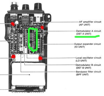
Documentation available on the net suggests tapping pin 11 of integrated circuit TK-10487 on "DET-A".
| However, when you open the radio it becomes clear how you
won't be able to solder directly on the IC, as it's located between two of those tight vertical boards.
More in detail, we're talking of the third from the right, pin 11 being on the main board's side.
|  |
| Luckily diagrams show how the NFM discriminator output is fed out from the DET-A board to reach
DET-B.
Signal is available on one of the pins connecting DET-A to the main board. Those can be easily reached
from below the main board, which can be unmounted removing the 4 screws indicated by red markings in the
image above and desoldering the lead from main board to antenna connector.
|
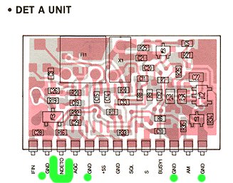 |
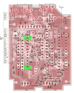
| Once the innards have been removed, looking at the bottom with battery pack towards you, DETOUT
is located on the third row of pins, third from the top. Solder one wire there and another on one of the
many available ground points. With a trunked radio control channel tuned I measured about 0,5V between
the two. I mostly get 100% signal quality reading on "Trunker" like programs, while a feed from the earphone
plug gives "no-signal" or 0%. |
 |
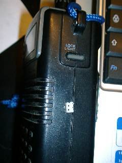
| I used part of a connector scavanged from a dead PC to make a socket on the right hand side of the
radio. You can definitely do a better job.
Remember to solder back the antenna lead when reassembling your receiver. |
 |
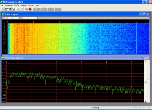
| Spectrogram of signal taken from earphone plug: the 0-200 Hz range is filtered out. |
 |
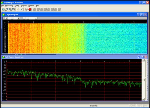
| Spectrogram of signal taken from discriminator tap. |
 |


